Building a £30 LISN for Conducted Emissions Debugging
One of our in-vehicle units failed conducted emissions at an external test lab, with the failing peak at ~460 kHz. Before making any changes to the unit, we wanted a way to see the emissions in-house, so we could find the source and know whether each change was actually an improvement, rather than paying for repeat lab sessions and going in blind.
The brief was to build a LISN. I spent about £30 on parts and it took around a week, including ordering and waiting for components. This post covers the design and build of the LISN itself; the testing it enabled, finding the source and fixing the failure, gets its own post: Measuring and Reducing Conducted Emissions: EN 55032 Failure.
This was never intended to be a fully compliant or precise tool. The goal was simply to reproduce the same emission peaks seen by the EMC lab, so that I could make relative before/after comparisons on the bench. It did exactly that.
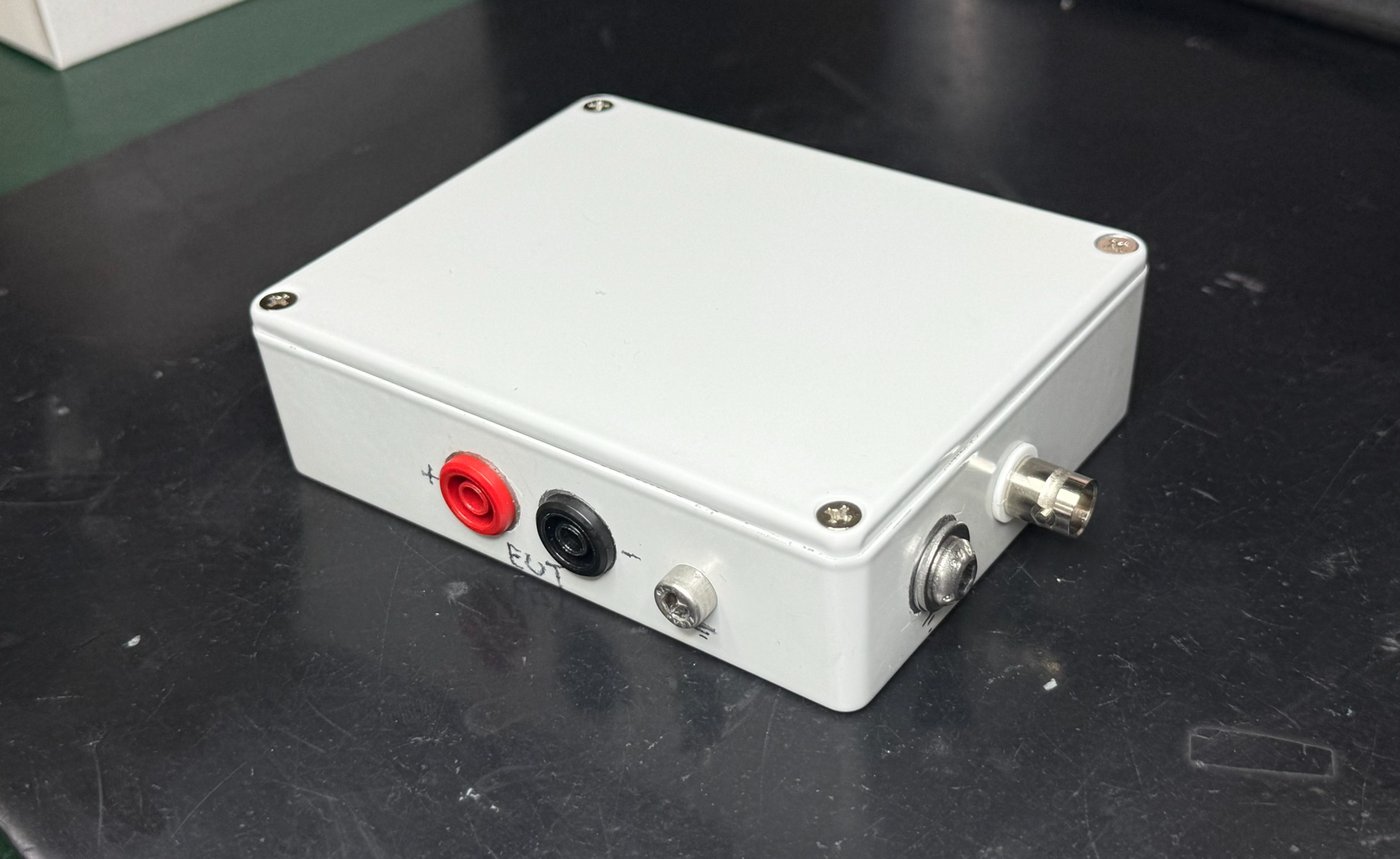
1. What a LISN actually does
A LISN (Line Impedance Stabilisation Network, also called an Artificial Network) sits between the power supply and the Equipment Under Test, and does two jobs:
- It presents the EUT with a defined, repeatable supply impedance, so results don't depend on whichever bench supply happens to be connected.
- It provides an RF measurement port to observe the noise the EUT pushes back onto its supply lines.
The 5 µH series inductance comes from CISPR 25 (the automotive EMC standard) and roughly mimics the impedance of a few metres of vehicle wiring harness. Without it, the switching noise from the unit just disappears into the low impedance of the bench PSU and there's nothing repeatable to measure.
2. From a rough sketch to CISPR 25
The starting point was the sketch from the original brief:
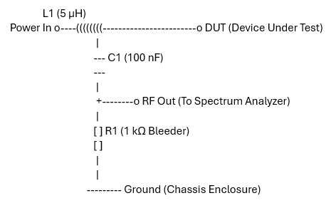
A 5 µH inductor in series with the supply, a 100 nF capacitor coupling the line to the RF output, and a 1 kΩ bleeder to chassis. I researched the topology properly before building anything, mainly using Tekbox's LISN Basics and Overview application note and CISPR 25 Annex E, Figure E.2, and a few things came out of that reading which changed the build:
- The sketch was missing the 1 µF source-side capacitor. This isn't optional: it shunts noise arriving from the supply to the reference (so you measure the EUT, not the bench PSU), and it shapes the LISN's impedance curve below 5 MHz. Tekbox's own 5 µH LISN requires one clamped across the source terminals.
- In Figure E.2, the "A" and "P" terminals are the same conductor: source side and EUT side of the inductor. "B" is the reference, not "the negative wire".
- The 50 Ω across the measurement port is not a component. The standard draws it outside the network because it represents whatever you connect to the port: the spectrum analyser's own 50 Ω input impedance, or a 50 Ω terminator when nothing is connected. If you solder a permanent 50 Ω resistor inside, it sits in parallel with the analyser (≈25 Ω), reads ~6 dB low and distorts the impedance curve. Easy trap.1
3. One network or two?
CISPR 25 uses the length of the EUT's ground return to decide the configuration: a short (under 200 mm) chassis return gets a single LISN in the positive line, while a longer return conductor gets two LISNs, one per line, which you measure one at a time with the idle port terminated in 50 Ω.
The lab measured both the live and ground lines and got near-identical results, and for diagnosis I only needed to reproduce the peaks. So I built a single artificial network on the V+ line, with the LISN's metal enclosure acting as the shared ground plane and both the PSU and EUT negatives bonded to it. This isn't the strictly compliant configuration for every grounding arrangement, but it was a deliberate simplification for a diagnostic tool, and it turned out to be all I needed. I never built a second LISN, though I kept a set of parts in case I ever do.
4. Grounding: one node electrically ≠ one wire physically
The most interesting part of the design for me was realising that the schematic and the physical build have to look different.
On the schematic, the enclosure, the PSU negative, the EUT negative, the bottom of the 1 kΩ and the BNC shell are all one node. Physically, joining them all with wire to a single point would be a mistake: any wire shared between the EUT's full return current (amps of switching ripple) and the microvolt-level measurement reference develops a voltage across its inductance, and that voltage lands directly in the measurement.
So I followed a different rule instead: bond each branch to the case separately, close to where it sits, and let the casting be the thing that joins them.
- I grounded the V− in and V− out terminals to the enclosure at their own studs, right next to each terminal. The return current flows through the case metal, which is milliohms, rather than through any shared wire.
- The bottom of the 1 kΩ and the BNC shell are the one exception: these are the two reference terminals of the measurement port, and any voltage between them reads as signal. I joined them directly to each other and then bonded that node to the case at a single stud. I used a flat copper strip rather than wire for this link, since for the same length a flat conductor has noticeably lower self-inductance than round wire (RF current flows on the conductor's surface).
- I fitted the 1 µF directly across the V+ and V− input terminals (which is also how Tekbox construct theirs), keeping its shunt loop short and local at the power end of the box.
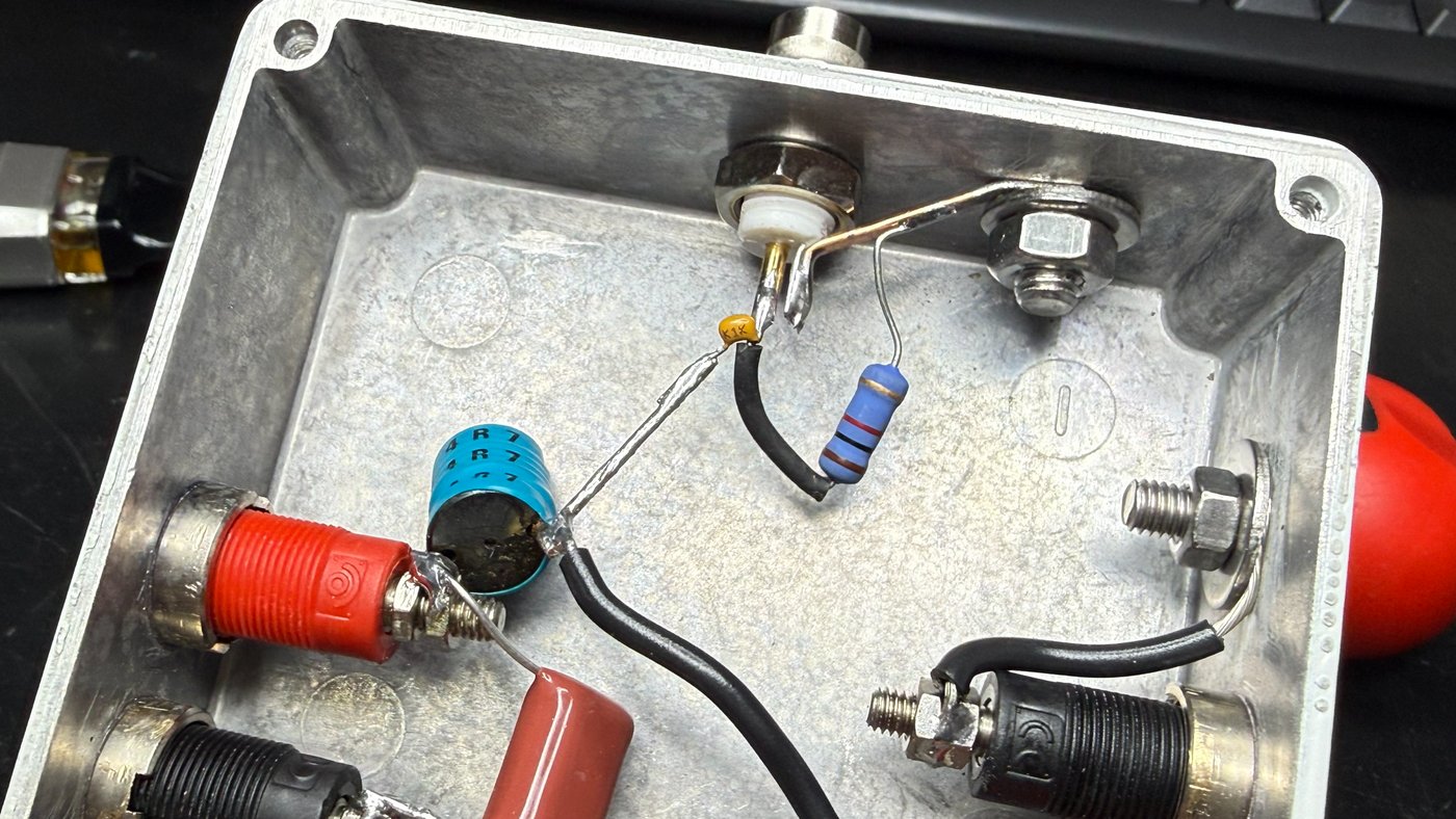
5. Parts
| Part | Part number | Cost |
|---|---|---|
| Die-cast enclosure (Hammond 1590BB) | 1590BB | £18.17 |
| Banana sockets ×4 (2 red, 2 black) | 3265-I-R / 3265-I-N | £4.36 |
| Inductor, 4.7 µH | SBC6-4R7-802 | £1.09 |
| 1 µF film capacitor | ECWF2W105JA | £0.82 |
| 100 nF capacitor | C320C104K1R5TA | £0.17 |
| 1 kΩ 2 W resistor | ROX2SJ1K0 | £0.14 |
| Isolated BNC connector | RS 546-4910 | £5.06 |
| Total | ≈ £29.80 |
A few notes on the choices:
The inductor is the honest one. The received wisdom for LISN inductors is to wind your own air-core coil: ferrite cores can partially saturate under DC bias, sagging below their nameplate inductance and generating harmonics that show up as emissions the unit never produced. I read all of that, and then fitted a £1.09 ferrite drum choke anyway. I chose the KEMET SBC6-4R7-802 for its through-hole profile, cost, and an 8 A current rating comfortably above the unit's ~2 A peak draw, and I ran it past our lead engineer, whose view was that it would do the job for what was needed. It did. I also bought a Würth 7447471047 as a backup but never needed to try it. The nominal value is 4.7 µH rather than 5 µH, which at ±20% tolerance overlaps the target anyway.2
The 1 µF is a metallised polypropylene film part (Panasonic ECWF, 450 V). Film rather than ceramic matters here: a Class 2 ceramic (X7R) loses a large fraction of its capacitance under DC bias, which would quietly shift the LISN's low-frequency impedance. 450 V is far more headroom than a 13.5 V rail needs, but the part was cheap and available.
The isolated BNC isn't actually required by the standard. CISPR 25 assumes a bonded ground plane throughout and never mentions connector isolation. But it decouples the shell from the mounting hole, so I decide where the shell bonds (via the copper strip to the single measurement stud) instead of the panel deciding for me. At £5 it was cheap flexibility.
6. The build
The enclosure is a Hammond 1590BB die-cast aluminium box: thick walls, low impedance everywhere, and solid enough that the "which stud goes where" question barely matters electrically. I drilled the holes on a drill press.
The detail that matters most on a painted die-cast box is surface preparation at every bond point. Paint and oxide are insulators, and a bolt through a painted panel gives a joint that measures fine on a multimeter and behaves badly at RF. For each stud I removed the paint in a ring around the hole on the outside, and scraped the oxidised layer off the casting on the inside, so the washers clamp onto bright metal on both faces. On the main stud I also used a tooth lock washer on the outside; the teeth bite into the metal and hold contact pressure as the joint settles.
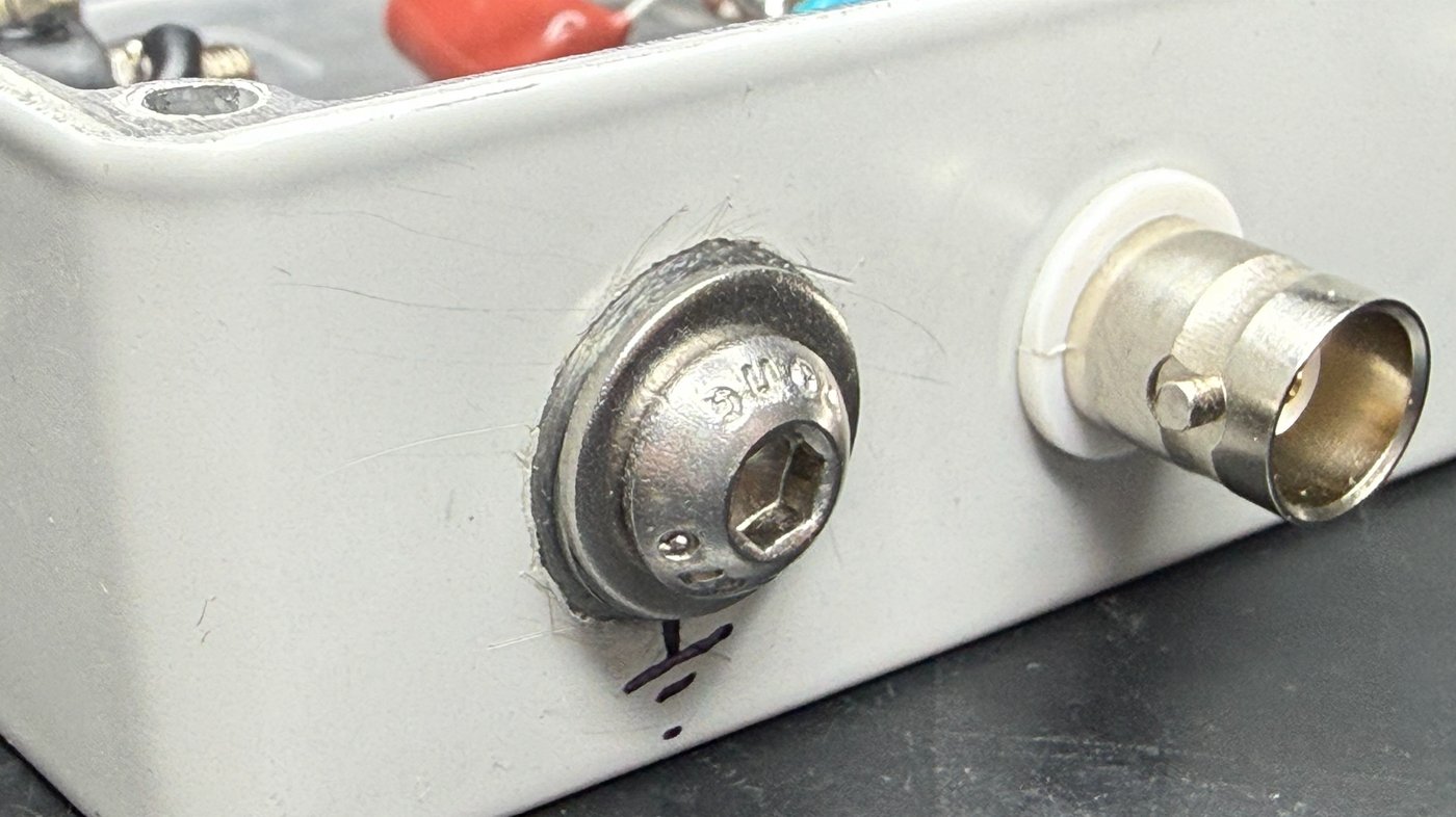
I marked both terminal pairs + / − (with the EUT pair labelled on the front face), and put each terminal's ground stud close to it.
7. As-built schematic
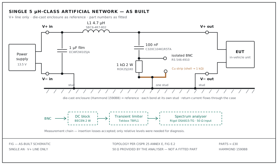
The spectrum analyser's input provides the 50 Ω load on the measurement port; there is no resistor inside the box.
8. The measurement chain
The RF port connects to the analyser through a DC block and a Tekbox TBFL1 transient limiter, into a Rigol DSA815-TG. The limiter is the non-negotiable part of the chain: switching supplies throw large transients at power on and off, and those go straight into the analyser's first mixer. As an extra habit, I always disconnected the RF cable from the analyser while powering the EUT on or off.
Both the limiter (a 10 dB pad by design) and the DC block introduce insertion loss, and the peak amplitudes I measured in-house sat slightly below the lab's as a result. I never corrected for this: the whole exercise only needed relative comparisons against a baseline, and the peaks were obvious regardless. I had planned to characterise and normalise the chain with the analyser's tracking generator, but in practice it was fine without.
9. Did it work?
Could my setup reproduce the spectrum the lab measured?
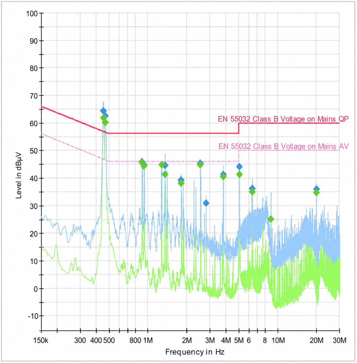
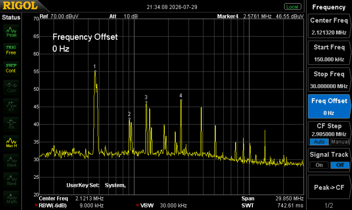
The same four peaks appear in both, at the same frequencies with the same relative structure. That was the entire success criterion, and it meant I could judge every subsequent experiment on the unit against a trustworthy baseline. That work is what the follow-up post covers: tracing the ~460 kHz peak to the unit's switching regulators and fixing it with input decoupling, which I verified on this LISN before re-test.
10. Limitations
- It's not calibrated. Absolute levels don't correspond to the lab's numbers (uncorrected chain losses, a non-compliant physical setup, no verified impedance curve). It measures relative emissions, which was the requirement.
- Single line only. One network on V+ with the enclosure as the shared reference: a deliberate simplification I justified with the lab's near-identical live/ground results.
- The ferrite inductor is unverified. I never measured it on an LCR meter or checked its behaviour under DC bias at full load. The reproduced spectrum suggests it behaved well enough at the frequencies that mattered (the problem lived below 3 MHz), but a wound air-core coil would be a better choice for anything closer to compliance work.
- The top end is unproven. KEMET don't publish the SBC6's self-resonant frequency; I treated the tool as trustworthy over roughly the 150 kHz to 30 MHz range I actually swept, and wouldn't lean on it much beyond that.
For a diagnostic tool built in a week for £30, against a commercial 5 µH LISN at roughly ten times the price or another external lab session, those are trades I'd make again.
Notes
- The "See 6.1.2" note on Figure E.2 refers to the termination requirement in CISPR 25 itself: the port must always see 50 Ω, whether that's the analyser or a terminator. ↩
- The SBC6-4R7-802 is 4.7 µH ±20%, so 5 µH sits inside its tolerance band anyway. For relative measurements the exact value shifts the impedance curve slightly but consistently, which cancels out of any before/after comparison. ↩